Goals
- Automatic Locking of a He-Ne Laser to Iodine Absorption Lines
- Fully remote operable from computer
- Less noise than in conventional systems -> shorter measurement time
- Offset errors due to electronics minimal
- Flexibility in research purposes
- Easy to use in calibration purposes
- Locking to any harmonic (3rd, 5th, 7th, ...)
- Modulation frequency tunable over a wide range
|
Implementation
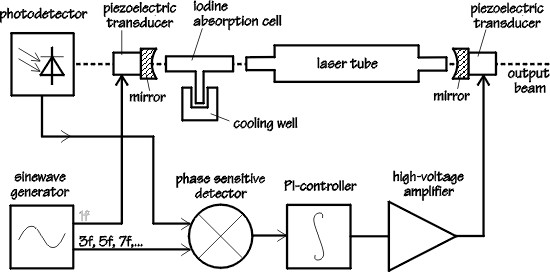
- Open DiLS HW diagram here
- Motorola DSP56002 40 MHz Digital Signal Processor
- 32k 24-bit DSP RAM
- 18-bit AD input to DSP (2 multiplexed channels)
- 18-bit DA output from DSP (2 parallel channels)
- Zilog Z-80 10 MHz CPU
- 64k RAM + 8k NV-RAM + 32k ROM
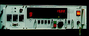
- 20x2 char LCD Display
- 4 char LED 7-segment Display (temp, frequency, voltage)
- Built-in PZT High Voltage Low Noise Power Supply & Amplifier
- RS-232 Connection to host computer
|
Statistics & Results
- Project started 11 April 1994
- First working version (DiLS 1c) ready 31 August 1995
- Developed novel algorithm (3hD) that uses dual phase detectors
to use the 3rd harmonic to stabilize 5th or higher harmonic locking
- 941 electronic components
- 16 circuit boards (1754 square centimeters)
- with 4043 drill holes, 1076 electrical nets, 90 meters PCB tracks
- 12690 lines assembler code (version DiLS 3a)
- 6464 lines C++ code
- Binary code in EPROM is 15014 bytes long (version DiLS 3a)
|